They applied curved beam theory Finite Element Method and photo elasticity experiments to obtain the stress field on the hook. Q 2 kNm² for varnished timber mould.
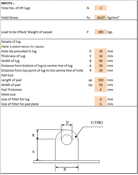
Lifting Lug Design Spreadsheet Calculator
This is calculated by dividing the bending moment on the lifting beam by its section modulus.
. There are also hooks that have a bearing or bushing at the top. Calculations to be made will include the capacity both of the overall beam and of the loading of the individual lifting points. See calculation example 3 below.
Ad ELT Incdesigns and manufactures Forklift Beams to ISO international standards. Therefore the requirement that special custom-design grabs hooks clamps or other lifting accessories be proof-tested prior to use is mandatory and failure to comply is a violation of OSHA requirements. The allowable bending stress is from AISC ASD F1-1.
Rdf ym 13 is the design shear strength and AR shdt hp 2 is the tearing out area. ASME BTH-1 specifies design calculations for different types of loading of a lifting device including tension compression flexure shear and combined loading of beams. 2 2 2 sinq long sling length.
Q 1 kNm² for oiled steel mould. Volume 1 24 cubic feet. Volume 1 Top 4 feet x 2 feet x 3 feet.
1 5 min 1 xi. Tension on Sling T 1 2 V1 2 H1 2 12 Tension on Sling T 1 2 W legs sin a 1 2 Tension on Sling T. The dimensions determinethe following length of the precast beam.
Q 3 kNm² for rough timber mould. Al 2009 this paper presents the different methods of stress calculation for lifting hooks based on different assumptions. Metric SI or English UK Units System can be selected for the calculation.
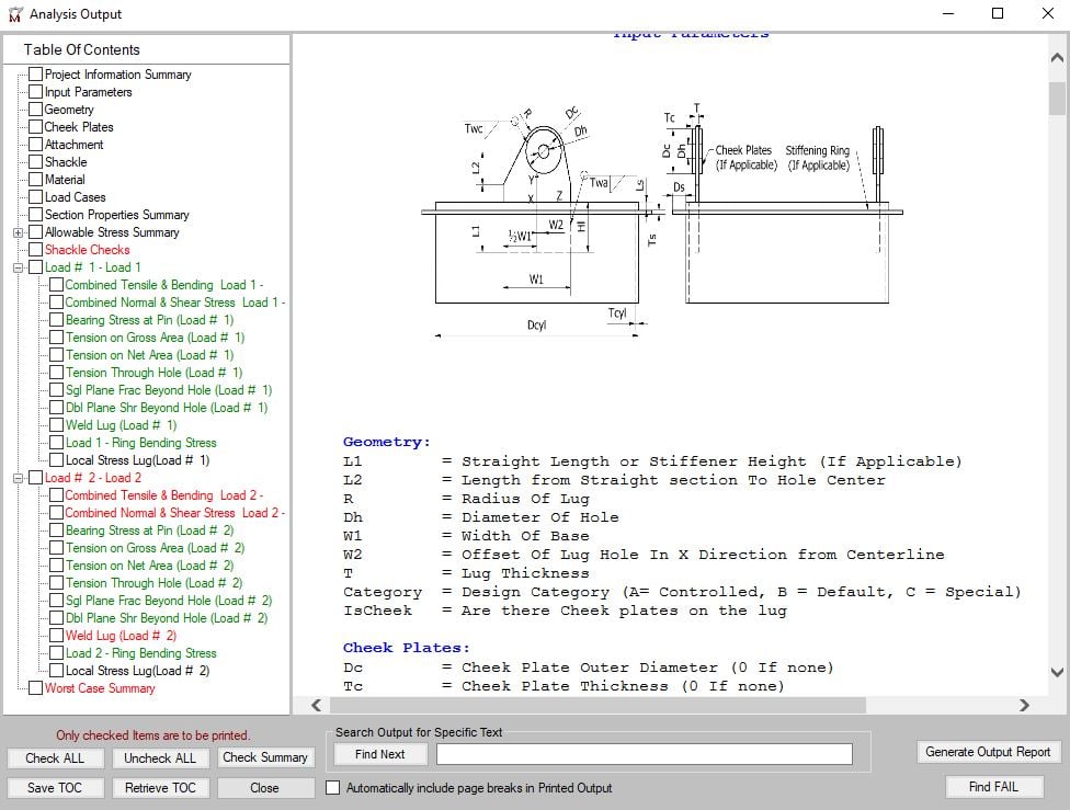
Lprecast L al ar 600m 005m 005m 610m The lifting hooks will be positioned at a distance from the edge of the precast part of eam equal b to 20 of the length of the precast beam. Call us for a quote today. Useful graphical views of the lug and welding are foreseen to better define the geometry and the dimensioning parameters.
The provisions in this Standard apply to the design or modification of below-the-hook lifting devices. Max 1 ξ V L. Lifting hook design calculation Written By alfonzostraney88785 Saturday March 26.
3C the sling lengths can be calculated using the following formulae. Lifting Hook Types Uses and Design Eye Hooks vs. Area of contact between the mould and the concrete unit when starting to lift.
Ha q x A kN A. There are two main ways a lifting hook or sling hook can be attached to the slingyou can either use a hook with an eye at the top or with a clevis at the top to make your connection to the sling. F y is the tensile yield strength of the plate material and γ m1 is the partial safety factor for the material specified by N-004 8.
Dividing these loads by the section area of the lifting beam gives the shear stress. Dynamic factor. The calculation includes the weight of the beam.
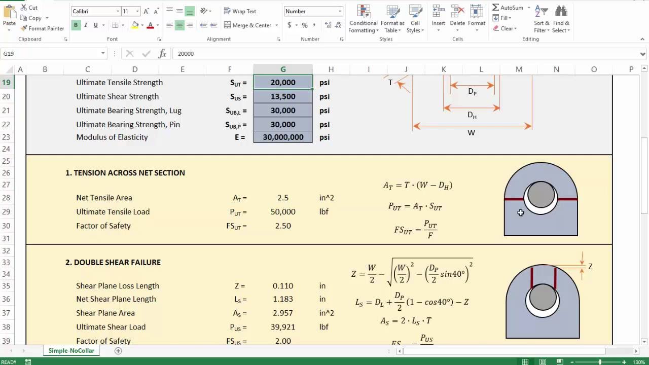
Lifting hook material Prestressing strands When prestressing strands are used Ultimate tensile stress Fpu 1860 Nmm2 Diameter of strand Dia 953 mm Area of prestressing strand As 5484 mm2 Yield strength of strand Fy n Fpu As 40801 kN DL 25050 kN b Anchorage length check. By varying the lengths of chokers a fixed-tilt lifting beam can be made as depicted in Fig. For producing a safe reliable design This is the most widely used lifting lug design standard.
The bending calculations include bar weight but do not account for shear stresses. Expressed in terms of variables noted in Fig. Another important consideration is the centre of gravity of the load to be lifted together with any accessories and or attachments used - slings grabs shackles hooks magnets vacuum pads etc.
The tension in the lifting leg will therefore increase from 2750 to 27501262 276262N as a result of the winch speed generating a DAF value of 276262 2750 10046 excluding added mass and drag considerations. In this particular example the hooks will be at 02610m122m. Lift capacity vs beam length based only on bar yield strength Gray Plot The allowable bending stress is a product of calculations from BTH-1 and the lift capacity is calculated from the allowable bending stress.
Heres how you would calculate the load weight of an irregular shaped object made out of concrete. BTH-1 provides minimum structural mechanical and electrical design criteria for ASME B3020 Below-the- Hook Lifting Devices. Compliance with requirements and criteria that may be unique to specialized industries and environments is outside.
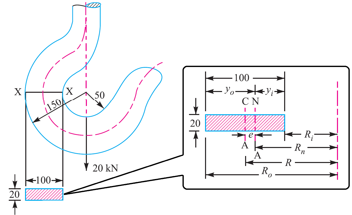
R represents the outer radius while d h is the hole diameter of the pad eye plate and t p is the thickness of the plate. First separate the object into rectangles and then calculate the weight of each section individually and then combine them as shown below. Formwork adhesion Ha is calculated through the following equation.
The quantity of effective lifting points may be less than the quantity of real lifting points if the system is not balanced. 115 with ξ 03 for fixed crane or on rails and ξ 06 for crane bridge. 2 a H Ha.
Welding verification between the lug and the bottom plate using the norm Eurocode 1993-1-82005 and NTC 2008. 1 a H Ha. However As such standards do not clearly address the local stress calculation steps Finite Element Analysis is performed using various.
From the above equations Calculated values The radius of curvature of the neutral axis R n 9107 mm The radius of curvature of the Centroidal axis R 100mm The distance between the Centroidal axis and Neutral axis e R-R n 100-9107 893 mm The distance between the centroidal axis to the load acting x R 100 mm. 115 min1ξmax1ξV L. To attach the load locate the center of gravity position the crane hook directly above the center of gravity and then rig the load so that it will lift level and true.
Proof Tested to exceed ANSIASME standards. As a result different methods used to obtain the stress field on. A lifting hook is a device for grabbing and lifting loads by means of a device such as a hoist or crane.
Depending on the style of lifting device only certain structural. Calculation of Actual Working Loads and arrangement of. A lifting hook is usually equipped with a safety latch to prevent the disengagement of the.
ASME BTH-1 Design of Below-The-Hook Lifting Devices governs the design of lifting lugs for industries. Min 1 ξ. Max 1 xi cdot V_ L.
Shear Stress the vertical loads on the lifting points cause shear stress.
Lifting Lug Design Mecalug Software Meca Enterprises Inc

Design Analysis And Weight Optimization Of Crane Hook A Review Semantic Scholar
2
4 Lifting Lug Analysis Simplified Youtube

Lifting Lug Design With Example What Is Piping
2

Technical Drawing Of Hook Number 12 Download Scientific Diagram
Crane Hook Design Problem Sample Extrudesign
0 comments
Post a Comment